
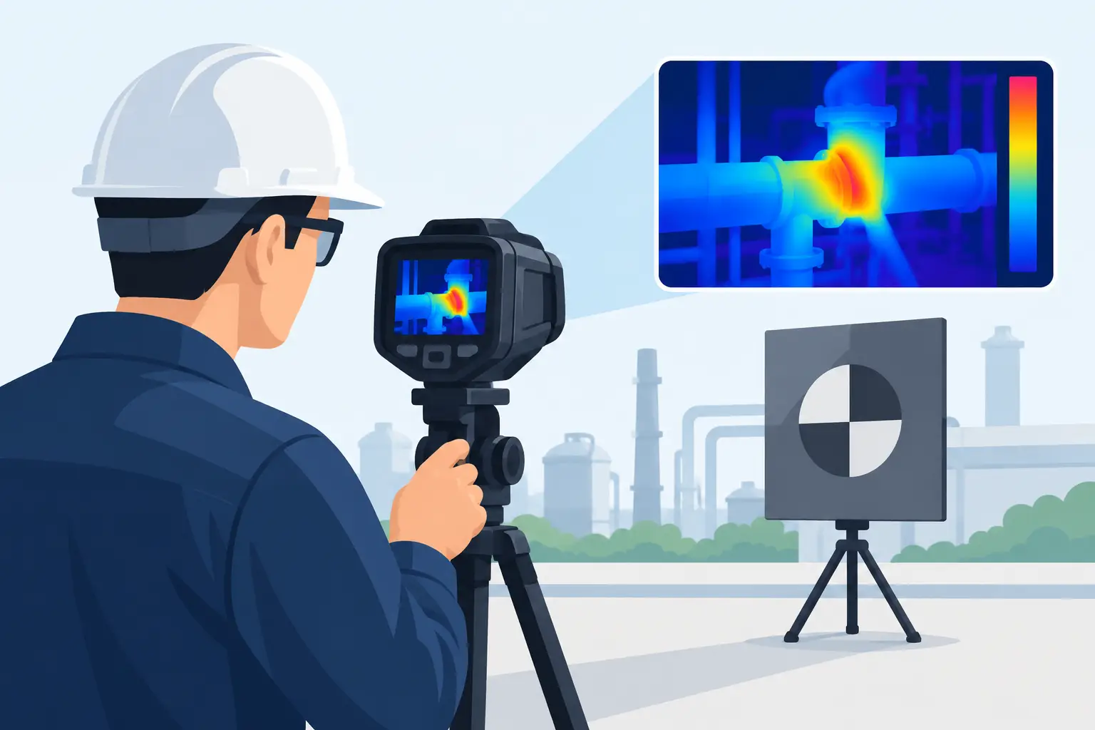
A missed hydrocarbon plume can turn a routine inspection into an unplanned shutdown, a safety exposure, or a costly emissions event. To calibrate gas imaging cameras correctly, operators need more than a quick power-on check. They need a controlled process that confirms the camera, lens, settings, environment, and inspection method are working together to reveal the gases that matter.
For refineries, offshore assets, chemical plants, terminals, and power facilities, calibration is not simply a maintenance task. It protects the value of the optical gas imaging investment by supporting repeatable findings, defensible records, and faster maintenance decisions.
What Calibration Means for Gas Imaging Systems
Gas imaging equipment does not behave like a standard security camera. It detects small infrared contrast differences between a gas plume and its background. That contrast changes with the gas being inspected, the temperature of surrounding equipment, sky conditions, humidity, wind, viewing angle, distance, and the selected lens.
For this reason, calibration has two levels. The first is manufacturer-level calibration, usually performed with specialized test equipment under controlled conditions. This confirms detector response, optical alignment, temperature stability, and system performance against the camera specification. Site personnel should not attempt to replace this process with field adjustments.
The second level is operational verification. This is the routine work performed before and during inspections to confirm that the camera is configured and behaving as expected at the asset. It includes checking image quality, focus, lens condition, internal correction functions, date and time settings, and the selected imaging mode for the target gas. Both levels matter. A properly calibrated detector can still produce weak inspection results if it is poorly focused, aimed at an unsuitable background, or used with the wrong configuration.
How to Calibrate Gas Imaging Cameras in the Field
A disciplined field process starts before the camera reaches the inspection route. Review the approved inspection procedure, target compounds, camera model, lens selection, and environmental limitations. Confirm that the system is designed for the gases and applications being surveyed. Not every infrared gas camera visualizes every compound with the same performance.
Start with Equipment Readiness
Inspect the enclosure, lens window, mounts, cables, power supply, and network connection. On fixed installations, verify that vibration, corrosion, salt spray, dust, or process residue has not compromised the housing or optical path. A dirty lens can reduce contrast enough to hide a small leak, while a loose mount can make plume movement difficult to distinguish from image motion.
Clean optical surfaces only with approved materials and methods. Then allow the camera to reach its specified operating condition. Thermal imaging systems need stabilization time, particularly when ambient temperatures are changing rapidly or equipment has been moved between controlled storage and an exposed process area.
Check the camera’s internal status indicators and complete any manufacturer-approved non-uniformity correction procedure. This correction helps compensate for small differences between detector elements. It is not a substitute for formal calibration, but it is essential to a clean, uniform image. Record any error messages, repeated correction failures, abnormal noise, or unstable imagery. Those are service triggers, not settings to work around.
Verify Focus, Scene Contrast, and Image Settings
Focus is one of the most common reasons for poor gas visibility. Focus on the likely leak zone or on an object at a similar distance, not on an unrelated foreground structure. Recheck it whenever the viewing distance, lens, or scene changes.
Next, assess the thermal background. A gas plume is seen because its infrared signature differs from what sits behind it. Clear sky, warm pipework, insulated equipment, shaded walls, or process vessels can produce very different results. A viewing angle that works well in the morning may be less effective after the sun heats the same equipment.
Use the camera settings validated for the target gas and inspection program. Automatic modes can be useful for initial scene assessment, but manual adjustment may deliver more consistent results across a route. Avoid aggressively changing contrast, gain, filtering, or image enhancement until the plume appears. Excessive processing can create misleading visual effects and makes results harder to compare from one inspection to the next.
Confirm Performance with a Controlled Reference
Where site procedures, permits, and safety controls allow, confirm performance against an approved controlled gas reference or test source. This should be planned and documented by qualified personnel. The purpose is not to prove an exact leak-rate measurement in the field. It is to demonstrate that the system can show an expected response under known conditions.
Document the gas type, source arrangement, distance, background, weather conditions, lens, settings, and results. If the expected response is absent or materially weaker than previous checks, stop and investigate. The cause may be a camera issue, a contaminated lens, an unsuitable background, incorrect configuration, or a problem with the test setup itself.
A controlled reference is especially valuable after repair, lens replacement, firmware changes, a significant impact event, or a long period out of service. For permanently mounted systems, verification should also follow major changes to the monitored area, including new pipework, altered lighting, or equipment that blocks the original field of view.
Environmental Conditions Can Change the Result
The same camera can produce different outcomes across a single shift. Wind can disperse a plume before it develops sufficient contrast. High humidity and atmospheric absorption can reduce effective viewing range. Rain, fog, steam, heat shimmer, and direct solar loading can all complicate interpretation.
That does not mean inspections should stop whenever conditions are imperfect. It means the operator must work within the camera’s limits and adjust the inspection position intelligently. If the background is poor, change the angle. If the plume may be moving across the scene too quickly, observe from another location. If a finding is uncertain, capture the conditions and repeat the inspection when a better thermal background is available.
For offshore and marine installations, add vessel movement, salt contamination, and vibration to the checklist. A stabilized mounting arrangement, protected cabling, appropriate environmental enclosure, and reliable network recording are part of detection quality, not separate conveniences.
When Field Checks Are Not Enough
Operational checks cannot correct detector drift, damaged optics, internal cooling faults, or deviations from factory performance specifications. Formal service calibration is required at the manufacturer’s recommended interval and whenever performance verification indicates a problem.
Send the system for qualified evaluation if images become consistently noisy, correction cycles fail, focus cannot be maintained, the camera no longer detects an approved reference under comparable conditions, or internal diagnostics show a fault. Procurement teams should factor calibration support, turnaround time, replacement coverage, and documentation into the total cost of ownership. A lower purchase price loses its appeal quickly if a critical inspection system is unavailable during a planned outage.
Maintain a traceable record for each unit. At minimum, include serial number, installation location, service history, factory calibration certificates where applicable, field verification results, operator name, environmental observations, and corrective actions. This record supports maintenance planning and gives operations leaders stronger evidence when prioritizing repair work.
Build Calibration into the Inspection Program
The strongest programs treat calibration and verification as routine controls, not emergency responses. Establish a pre-use checklist, a defined verification interval, clear acceptance criteria, and an escalation path for questionable results. Train operators to recognize the difference between a genuine gas plume, thermal turbulence, reflected radiation, moving shadows, and compression artifacts in recorded video.
For fixed gas imaging deployments, integrate camera health monitoring with the site’s surveillance and network infrastructure. Remote access, event recording, image retention, and reliable power protection help teams review evidence quickly without sending personnel into hazardous areas unnecessarily. The best system is not just a top-of-the-line camera. It is a managed detection capability that delivers useful evidence when operations need it.
Revlight Security supports industrial buyers who need gas detection and surveillance equipment selected around real operating conditions, not generic specifications. The correct camera, lens, enclosure, mounting position, and support plan should be determined together.
A calibrated gas imaging camera earns confidence one inspection at a time. Give operators a verified system, a suitable background, and a documented process, and they can turn infrared imagery into faster, safer maintenance decisions.
🛡️ Secure Your Home or Business Today
Protect your home, office, shop, or business with reliable CCTV security cameras. Explore our range of CCTV cameras and find the right security solution for your needs.
Explore CCTV Cameras ✉️ Email Us

 Singapore :
+65-6708-9302
Singapore :
+65-6708-9302