
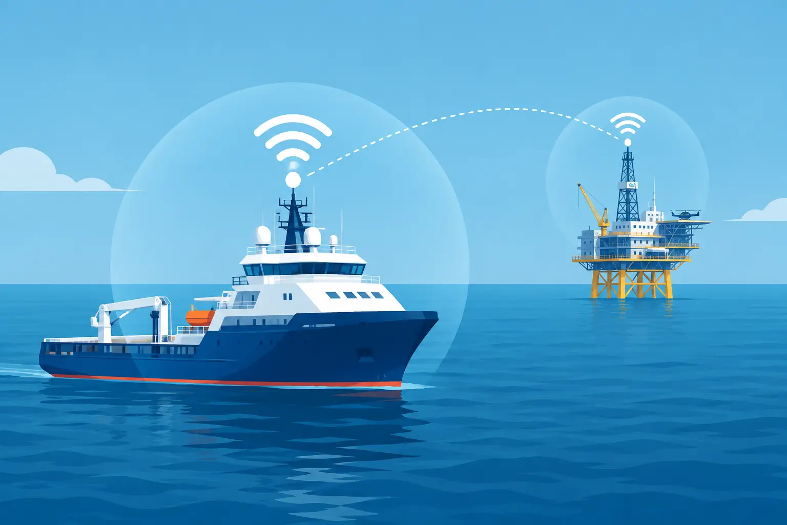
A dropped connection at sea is rarely just an inconvenience. It can interrupt CCTV review, delay maintenance reporting, prevent crew communication, and leave bridge or engineering teams without access to critical network resources. Marine wifi range is therefore a design question, not a single product specification. The right result depends on distance, antenna height, vessel movement, obstructions, RF noise, bandwidth demand, and the quality of the equipment installed at both ends of the link.
For ship operators, offshore facilities, and industrial marine sites, a properly specified wireless network can reduce cabling work, extend surveillance coverage, and provide dependable access across decks, docks, workboats, and nearshore assets. But claims of extreme range mean little unless the installation conditions support them.
What Determines Marine WiFi Range?
Marine WiFi range is the usable distance between wireless devices while maintaining the throughput and stability required for the job. A connection may technically appear at a long distance, yet deliver too little capacity for video streams, remote access, or reliable operational traffic. Procurement teams should assess usable performance, not simply whether two radios can detect one another.
The first factor is line of sight. Wireless signals perform best when there is a clear path between antennas. Radar masts, cranes, containers, bulkheads, exhaust stacks, and even changing cargo arrangements can block or reflect the signal. On a vessel, these obstacles are not fixed in the same way they are at a shore facility. A network design must account for operational configurations, not just an empty-deck survey.
Antenna placement matters just as much. Raising an antenna can improve the radio horizon and clear local obstructions, but higher is not automatically better. Long cable runs introduce signal loss, and an antenna mounted beside high-power transmitters or metal structures can suffer interference and reflection. The most effective position is one that provides a clear path, controlled cable length, safe service access, and separation from known interference sources.
Frequency selection is another practical trade-off. Lower-frequency wireless bands generally travel farther and handle some obstructions better, while higher-frequency bands can support greater capacity where the path is clear. A vessel requiring basic operational connectivity over a wider area may have different needs from an offshore platform transmitting multiple high-resolution surveillance streams. There is no universal best band. The correct choice follows the application and site survey.
The Sea Does Not Create a Perfect Radio Path
Open water can create a false sense of simplicity. With few buildings in the way, users may expect exceptional distance. In reality, water reflects radio energy, and the combination of direct and reflected signals can cause fading. Vessel pitch, roll, yaw, tide changes, and wake movement can also shift antenna alignment. Weather may not stop a well-designed wireless link, but salt exposure, wind loading, condensation, and corrosion will quickly expose weak hardware and poor installation practices.
This is why industrial-grade enclosure ratings, marine-suitable connectors, corrosion-resistant mounting hardware, and properly sealed cable entries are part of range performance. A radio cannot maintain a long link if moisture enters a connector or a bracket loosens after months of vibration.
Specify Marine WiFi Range by Application
The required range should begin with the operational area that needs coverage. A harbor-side vessel connection has different design limits than a point-to-point link between offshore structures or a wireless extension to a dock perimeter. Treating each as the same requirement creates expensive gaps.
For onboard coverage, the primary challenge is usually penetration around steel bulkheads and through compartment layouts. Multiple access points are often more effective than one high-power unit attempting to cover every deck. This approach creates stronger local coverage, improves roaming for authorized users, and gives security teams more predictable connections for networked surveillance equipment.
For vessel-to-shore connectivity, the main considerations are distance from berth, shore antenna elevation, competing wireless networks, and the need to maintain service while the vessel shifts position. Directional antennas can provide a focused, longer-distance connection when alignment is controlled. Where a vessel is regularly alongside or within a defined anchorage zone, a planned shore-side network can deliver far better results than relying on consumer-grade equipment.
For offshore point-to-point links, capacity and availability become central. A connection that supports messaging may not support continuous video recording, remote playback, or several concurrent monitoring feeds. The system must be sized for actual traffic, including protocol overhead, peak usage, and future expansion. A conservative design leaves headroom instead of operating at the edge of its claimed capacity.
Range Figures Need Context
Suppliers sometimes state wireless distance in miles or kilometers without explaining the conditions behind the number. Those figures may assume a clear path, carefully aligned directional antennas, low RF interference, correct channel planning, and a throughput level that is not suitable for demanding applications. Such numbers can be useful for comparison, but they are not a deployment guarantee.
A serious specification should ask for the expected link distance, required throughput, antenna type, mounting height, environmental rating, power arrangement, and network topology. It should also state whether the link will carry surveillance video, operational data, guest access, voice services, or a combination of traffic types.
Video is particularly demanding because performance problems can appear as frozen images, delayed playback, reduced frame rates, or recording gaps rather than a complete outage. If a wireless link supports security cameras, calculate bandwidth from the camera count, resolution, compression method, frame rate, retention workflow, and expected simultaneous viewing. Then design the wireless backbone with margin for maintenance access and future camera additions.
Build the Network Around Reliability
The strongest marine wireless systems are built in layers. A long-distance bridge connects separated locations, local access points distribute service around the vessel or facility, and managed switching and routing control traffic between operational, security, and crew networks. Segmentation is not a luxury. It protects critical systems from congestion and prevents a general-use device from creating a weak point in a security network.
Power resilience also deserves attention. Wireless equipment should be connected through suitable protected power infrastructure, with backup where the application requires it. A network outage during a power event defeats the purpose of remote monitoring. Equipment selection should consider PoE requirements, available power budget, surge protection, grounding strategy, and access for maintenance.
Remote management provides a major operational advantage. Network administrators should be able to review device health, signal quality, client activity, channel utilization, and link throughput without sending a technician to the mast or outer deck for every issue. Alerting can identify a degrading link before it becomes a lost connection, helping operators schedule service during planned maintenance instead of responding to an urgent failure.
Security Cannot Be Added Later
A long-range wireless signal that extends beyond the vessel or facility perimeter must be protected accordingly. Strong encryption, controlled credentials, separated VLANs, firmware management, and access logging are baseline requirements for industrial deployments. Default passwords and unmanaged equipment are unacceptable where wireless infrastructure carries surveillance, operational, or corporate traffic.
The right system also makes it easier to control who can connect and what they can reach. Crew connectivity, contractor access, visitor devices, CCTV traffic, and engineering systems should not all share unrestricted access to the same network segment. Clear policy and network separation protect availability as well as data.
A Better Buying Process
Before requesting a quotation, document the distances, assets, mounting points, traffic requirements, power availability, and environmental conditions at the site. Include photographs or drawings that show likely obstructions and identify nearby radio equipment. This information allows a supplier to recommend the correct radios, antennas, enclosures, mounts, and network components instead of offering a generic range claim.
Ask how the proposed system will be tested after installation. Acceptance testing should confirm signal level, throughput, latency, stability, coverage areas, and performance under the intended workload. For surveillance applications, test live viewing, recording, playback, and remote access at the same time. The installation is only complete when the network supports the operation it was purchased to protect.
Revlight Security supplies marine wireless and security infrastructure for operators that need dependable coverage in demanding environments. The objective is not to sell the longest advertised distance. It is to provide the right wireless architecture for secure communication, surveillance continuity, and operational control.
A well-planned marine wireless installation turns range from a marketing number into a measurable operating result. Start with the coverage and performance your crews need, then specify equipment and installation standards that can keep delivering when the vessel moves, the weather changes, and the network is under real load.
🛡️ Secure Your Home or Business Today
Protect your home, office, shop, or business with reliable CCTV security cameras. Explore our range of CCTV cameras and find the right security solution for your needs.
Explore CCTV Cameras ✉️ Email Us


 Singapore :
+65-6708-9302
Singapore :
+65-6708-9302